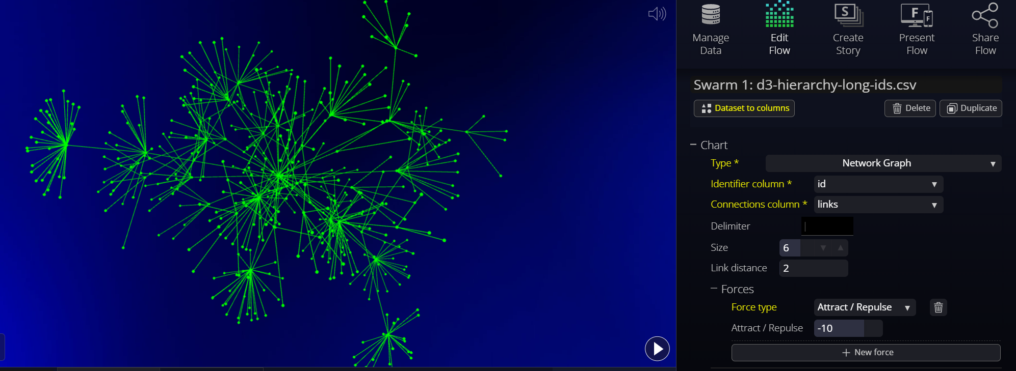
Network Graphs
A network graph shows data points,points or nodes,(nodes), associated together by links,links or edges,(edges) to seeindicate relationships between data in directed graphs or hierarchies.
Flow uses a force-directed graph algorithm to create Network Graphs. This is based on the D3 implementation of force-3d. The implementation in Flow can be pretty straightforward or more sophisticated in nature. For many cases, the default settings are adequate to show quitebeautiful beautifuland informative graphs. If you'd like to read more about the original D3 algorithms, this is a good explanation.
Dataset preparation
Dataset preparation can be complicated and may require programming skills at this time. The dataset that will showfor a network graph must contain a row for each node in the graph. The row must contain an "id" column which must be unique for every row in the dataset,dataset. and The row must also contain a "connections by id" column which lists the ids of every rowother node that the node is to be connected to.
*** The link below must be regenerated.

In the above example, the Network Graph has 10 nodes, and nodes A, B, and C have connections to nodes 1 through 6 as indicated by the connections column. The connections column requires a list of ids, separated by the "|" pipe character (SHIFT-backslash on most keyboards).
*** The link below must be regenerated.

For more on How to get from Flat Data to a Network Graph, see https://docs.flow.gl/books/flow-documentation/page/how-to-get-from-flat-data-to-a-network-graph
Forces
NOTE: if you are adjusting parameters and not seeing any difference, it is likely because other forces are overwhelming the parameter you are updating. Experiment with other parameters as well.
The graph is created by "forces" that iteratively push and pull on each other, so the nodes algorithmically create patterns based on the links present.
The default force is a "link force" which has an attraction force (strength) between connected nodes. If we just apply a link force, the connected nodes will be attracted toward each other, but there will be no forces repelling non-connected nodes.

To remedy this, we can add either Attract-Repulse or Anti-collision forces.
In addition to strength, link distance is the suggested distance between nodes, an important parameter that will dictate how closely clustered our graph will end up, although it could be overcome by Attract-Repulse forces.

NOTE: if you are adjusting parameters and not seeing any difference in the network graph, it is likely because other forces are overwhelming the parameter you are updating. Please experiment with other parameters as well.
Anti-collision
If we instead want our nodes to interact and collide off one another, we can use force type “collision”. This will keep any two dotsnodes from getting too close to each other.
The main parameter of Anti-collision is the spacing around our nodes where the collisions should occur. If our nodes have a radius of 8, we'll probably want to make the collision radius the same (or slightly larger to provide some padding).

Spherical
The Spherical force is a force to push the dots away from the center of the swarm, makingcausing the network graph to take a spherical shape.
This is based on the "radial" force in d3, but applied to all three dimensions.

Attract / Repulse
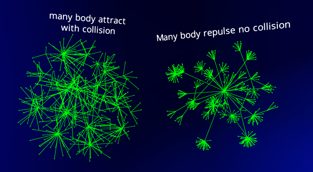
We can also have our nodes interact with one another using an Attract-Repulse force. (This is similar to the anybody force in d3). This means the force in question is applied on each combination of nodes (many-to-many). We can simulate node attraction with positive numbers (similar to oppositely charged particles) or node repulsion with negative numbers (like similarly charged particles). Example values:
- Strong attraction (strength = 2)
- Weak attraction (strength = 1)
- Weak repulsion (strength = -5)
- Strong repulsion (strength = -30)
If we use a positive strength (attraction), you'll notice that as the nodes attract to one another, they will overlap like our initial version of using the x and y forces. As we did before, if we don't want that, we can simply apply a collide force in addition to our many-body force.
You can end up with a similar but different layout by using Attract / Repulse on its own with a repulsion setting, vs. Attract/Repulse attract (positive values) combined with Anti-collision to then separate the points from each other.
Flatten Depth / Width / Height
These three "flatten" forces will attract the dots to a particular plane and can give a 2-and-a-half-dimension look. It is handy if you want to have the graphs look somewhat flatter to work better on flat screens while keeping some of the advantages of 3D.
Shown from the side:

Shown from the front:
